
Thursday, August 15, 2013
More Mura Filter
Monday, August 12, 2013
Monday, July 8, 2013
Electronic Kick Drum Mods

Monday, June 24, 2013
Microcontrollers

I let them sit for about a year. Part of the reason is I had not used them is that I had purchased a PICKit 2 after reading reviews on the web. The PICKit is required to program a microcontroller. First of all the software on the disk they sent with it was corrupted. That turned out not to be a problem since you can download it from Microchip's web site. Next I was having trouble with my computers and had to install Ubuntu Linux on one of them. Then when I did try to program something the lights would flash and it would lock up. It also took me a while to find some tutorials at the appropriate level for me.
I finally got these to work last weekend. One of the keys was the system was not detecting the boards. After I had reseated the programmer and chip a few times it suddenly started working. The contacts on these must be poor.
Last week I was teaching a class on STEM based on RC race cars. I thought it would be good to have the students make a circuit that was related to racing, so I thought a red, yellow, green symbol similar to drag racing would be good. My initial circuit design was all analog. This started to get bigger and bigger and I finally thought I would investigate the microcontrollers again.
I always like to start small when I learn something new so the first step was to get an LED to turn on. It turns out that the PICKit 2 doesn't turn on the LEDs with 8 pin chips but you can run a jumper from the output over to the LED. Also it turns out that GP3 is input only so you can't use that to turn on an LED. The chip refused to work with my capacitor based rail splitter and a 9V battery so I ended up having to use a voltage regulator to deliver 5 V to the chip. Some programming later and it started turning on the LED and shortly afterwards I had a simple stop light circuit (see figure). This should enable me to press a button, have the lights go through a sequence, then hold on green until I press a button again.
For musical applications these could be used to trigger gates for devices to turn them on. I should be fairly straightforward to implement.
#if defined(__XC)
#include <xc.h> /* XC8 General Include File */
#elif defined(HI_TECH_C)
#include <htc.h> /* HiTech General Include File */
#endif
#include <stdint.h> /* For uint8_t definition */
#include <stdbool.h> /* For true/false definition */
//#fuses NOMCLR,NOPROTECT,NOWDT,INTRC
#pragma config MCLRE=OFF,CP=OFF,WDTE=OFF,FOSC=INTOSCCLK
#define _XTAL_FREQ 4000000
uint8_t sGPIO;
void init()
{
//Configure GPIO Port
ANSEL = 0b00000000; //Configure all GPIO pins as digital
TRISIO = 0b11111000; //Set GP0, GP1, GP3 as outputs and the rest as inputs
WPU = 0x00; //Disable weak pullups
//Configuer AD Convertor
ADCON0 = 0x00; //AD disabled
ADRESH = 0x00; //Init the AD Register
//Configure Comparator
CMCON0 = 0xFF; // Comparator is turned off
CMCON1 = 0x00; // Comparator is turned off
//Interrupt configuration
INTCON = 0x00; //Disable all interrupts
}
void main()
{
uint8_t db_cnt;
init();
GPIO = 0b00100000;
sGPIO= 0b00100000;
while(1)
{
GPIO = 0b00100000;
for (db_cnt = 0; db_cnt <= 5; db_cnt++)
{
GPIO = 0b00100001;
__delay_ms(40);
GPIO = 0b00100000;
GPIO = 0b00100010;
__delay_ms(40);
GPIO = 0b00100000;
GPIO = 0b00100100;
__delay_ms(40);
GPIO = 0b00100000;
}
__delay_ms(1000);
for (db_cnt = 0; db_cnt <= 10; db_cnt++)
{
__delay_ms(10);
if (GPIObits.GP5 == 1)
db_cnt = 0;
}
GPIO = 0b00100001;
__delay_ms(1000);
GPIO = 0b00100000;
GPIO = 0b00100010;
__delay_ms(1000);
GPIO = 0b00100000;
GPIO = 0b00100100;
__delay_ms(1000);
for (db_cnt = 0; db_cnt <= 10; db_cnt++)
{
__delay_ms(1);
if (GPIObits.GP5 == 1)
db_cnt = 0;
}
}
}
Wednesday, June 5, 2013
Neutron Flux Detector
This piece consists of a sequence from the DSI Evolver sequence for the introductory sound, with a Korg MS2000 processed with a Moogerfooger Phaser and doubled with a Waldorf Pulse processed by a Lexicon Vortex, Moog Little Phatty plays the lead part (Vaguely Vocal) sweeping the filter with a foot pedal.
Monday, June 3, 2013
Sunday Synth Jam

Saturday, June 1, 2013
4093 NAND MiniModular

I got the idea to do a mini modular based on the 4093 NAND chip. I decided to use each of the gates as an oscillator. The three knobs across the top control frequency, control voltage, and output amplitude respectively. The first switch puts some lag on the input control voltage, the second switch changes the oscillator to LFO mode and the third switch switches between continuous and gate mode. These controls are repeated four times for each of the NAND gates on the chip. The top control is a starve connected to the supply voltage so I can reduce the overall voltage supplied to the device. I made it 1/8" so I could connect to the upcoming MS20.
This video demonstrates the device in operation.
I also tried connecting this to using a keyboard by using the Cv and gate outputs from my Pulse synth. This worked out well for the gate but the pitch does not change much with the output voltages, about one note per octave.

Saturday, April 27, 2013
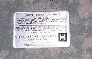
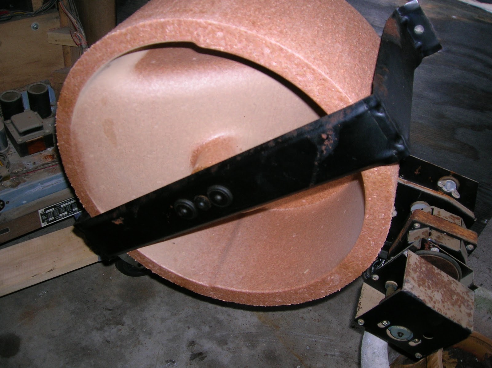
Work on the Hammond T-422
Some nice weather today so I did some work on the Hammond. This beast is way to heavy to carry around and I don't really have room for it in my house so my current plan is to modularize all of the individual components. These are some shots of the built in Leslie unit. The cylinder is made of what appears to be a polystyrene or related polymer although it seems a bit tougher than styrofoam. Looks like a two motor system.


Is that about a 5" speaker? Maybe that could be upgraded. Thinking about a using a stepper motor for this but I might not be able to get enough torque. Either that or build a preamp and power supply for this and mount it in a separate cabinet.


Is that about a 5" speaker? Maybe that could be upgraded. Thinking about a using a stepper motor for this but I might not be able to get enough torque. Either that or build a preamp and power supply for this and mount it in a separate cabinet.

Started cleaning all the gunk off this board and discovered it is the drum module. This was still working during my initial test. Found a piece of wire or solder underneath this board which may have resulted in some shorting. Needs more cleaning. I was originally thinking of trying to rig this up to a techno style drum machine. Maybe I can convert those trim pots to knobs. I may have to reflow the solder on a couple points.

Reverb tank looks intact and has standard connectors. I think I will try it out with my Blues Jr.


Wednesday, April 24, 2013

Saturday, April 6, 2013
VSF Video Demos
Here are a couple demonstrations of my new filter design the VSF.
Got the transistors working now. Changed the resistors to 10k and switched to 3904s.
Got the transistors working now. Changed the resistors to 10k and switched to 3904s.
Tuesday, April 2, 2013
VSF

Finished building the VSF (described below) last night. I had to disable the transistors since they seemed to be on continuously. Very nice distorted complex tone colors out of this thing. I need to change the pots to 100k from current 1M for VCF and 500k for Q. The Mura I need to change from 100k to 1M. Go figure. I will try to get an example of the sound up here soon. I may try to change the transistors so I can get some control voltage response.
Monday, April 1, 2013
Mura Filter

Falstad circuit simulator code:
$ 1 5.0E-6 0.9891409633455756 50 5.0 50
r 336 320 272 320 0 4700000.0
c 336 224 336 192 0 1.0E-9 0.00268564673175871
c 432 224 432 192 0 1.0E-9 -1.876367065692067
r 272 320 272 368 0 47000.0
c 272 320 224 320 0 1.0000000000000001E-7 -2.4144869775373956
174 336 192 432 176 0 100000.0 0.9059 Q 100k
a 336 336 432 336 0 15.0 -15.0 1000000.0
w 336 224 336 240 0
w 336 288 336 320 0
w 432 224 432 240 0
w 432 288 432 336 0
g 336 352 336 368 0
g 272 368 272 384 0
O 432 336 432 368 0
174 336 192 240 176 0 100000.0 0.9257000000000001 Fco 100k
g 240 192 240 208 0
w 288 176 336 192 0
R 224 320 192 320 0 2 100.0 5.0 0.0 0.0 0.5
r 336 288 384 288 0 2000000.0
r 384 288 432 288 0 2000000.0
g 384 240 384 224 0
c 384 288 384 240 0 1.0E-11 -0.939194425306891
w 384 176 336 192 0
w 432 240 432 288 0
w 336 240 336 288 0
w 336 160 336 192 0
w 448 288 432 288 0
174 336 160 432 160 0 1000000.0 0.005 Resistance
d 464 160 464 192 1 0.805904783
w 384 144 336 160 0
w 432 160 464 160 0
w 464 192 464 288 0
w 464 288 448 288 0
t 288 128 288 160 0 1 0.45948822583066745 0.4568213771495246 100.0
w 272 160 240 160 0
w 240 160 240 192 0
w 304 160 336 192 0
R 288 96 288 64 0 1 40.0 3.0 2.0 0.0 0.5
174 288 96 304 128 0 1000000.0 0.10400000000000001 Resistance
w 304 112 288 96 0
o 13 4 0 34 20.0 9.765625E-5 0 -1

Note the resonance wave form has a slight sawtooth edge as well as only oscillating on the positive cycle of the square wave.
Sunday, March 24, 2013
Very Strange Filter 2

I decided to put this into a case. I get these boxes at Office Max for about $1.50. They drill out pretty easily with the Dremel dry wall attachment. Have all the hardware attached at this point but still need to add the wires.

The top of the box.

This shows the circuit board in the box. No wires attached yet but all of the components are in place. This is basically a three part filter. Probably a bit silly of me to make this without breadboarding it first since I don't really know what it will sound like.
Thursday, March 14, 2013
Pendula
Created some sound in Csound based on this video I found on Youtube:
https://soundcloud.com/hmikelson/pendula
<CsoundSynthesizer>
<CsOptions>
;-RWfo pendula.wav
</CsOptions>
<CsInstruments>
;---------------------------------------------------------
; Pendula
; Inspired by Youtube video of pendulums of various lengths like this one
; http://www.youtube.com/watch?v=eZm_-2O8ovI&list=UUeQEKFH31vvD-InkTGSvCrA
; Hans Mikelson March 2013
;---------------------------------------------------------
sr = 44100 ; Sample rate
kr = 44100 ; Kontrol rate
ksmps = 1 ; Samples/Kontrol period This must be 1 to make sure to update time appropriately
nchnls = 2 ; Normal stereo
;---------------------------------------------------------
; Pendula
;---------------------------------------------------------
instr 50
idur = p3 ; Duration
iamp = p4 ; Amplitude
il0 = p5 ; Length of pendulum
ib = p6 ; Damping factor for pendulum (smaller damping will ring longer)
ig = p7 ; Gravity
kdclk linseg 0, .005, 1, idur-.01, 1, .005, 0
atime init 0 ; Need to start time at 0
atime = atime + .1 ; Time is incremented each sample
ialpha0 = ib/2/il0 ; Calculate alpha exponential decay factor
aamp0 = 1*exp(-ialpha0*atime) ; Calculate exponetial decay
aout0 = aamp0*cos(sqrt(ig/il0-ib/il0/il0)*atime) ; Calculate the oscillator times amplitude
apan = .5 + aout0/2
outs aout0*iamp*apan*kdclk, aout0*iamp*(1-apan)*kdclk ; Amplify and output
;outs aout0*iamp*sqrt(apan)*kdclk, aout0*iamp*sqrt(1-apan)*kdclk ; Amplify and output
;outs aout0*iamp*kdclk, -aout0*iamp*kdclk ; Amplify and output
endin
</CsInstruments>
<CsScore>
;-------------------------------------------------------------------------
f1 0 65536 10 1
; Pendula
; Sta Dur Amp PendL Damp Gravity
i50 0.0 10 3000 100 0.02 9.81
i50 . . . 90 . .
i50 . . . 80 . .
i50 . . . 70 . .
i50 . . . 60 . .
i50 . . . 50 . .
i50 . . . 40 . .
i50 . . . 30 . .
i50 . . . 20 . .
i50 . . . 10 . .
; Pendula
; Sta Dur Amp PendL Damp Gravity
i50 10.0 10 3000 100 0.02 9.81
i50 . . . 95 . .
i50 . . . 90 . .
i50 . . . 85 . .
i50 . . . 80 . .
i50 . . . 75 . .
i50 . . . 70 . .
i50 . . . 65 . .
i50 . . . 60 . .
i50 . . . 55 . .
; Pendula
; Sta Dur Amp PendL Damp Gravity
i50 20.0 5 3000 200 0.1 9.81
i50 . . . 100 . .
i50 . . . 50 . .
i50 . . . 25 . .
i50 . . . 12 . .
i50 . . . 6 . .
; Pendula
; Sta Dur Amp PendL Damp Gravity
i50 25.0 5 3000 100 0.05 9.81
i50 . . . 90 . .
i50 . . . 81 . .
i50 . . . 73 . .
i50 . . . 66 . .
i50 . . . 59 . .
i50 . . . 53 . .
i50 . . . 48 . .
i50 . . . 43 . .
i50 . . . 39 . .
</CsScore>
</CsoundSynthesizer>
Saturday, March 9, 2013
Wednesday, March 6, 2013
Planar Crystal Live Rig

My planar Crystal live rig consisting of Waldorf Pulse processed by Lexicon Vortex, Korg MS2000, MPC500 for sampling and sequencing, Thing 2 and Sequencer processed by Kaoss Pad. Midi clock originates with MPC500 and controls arpeggiator speed on MS2k, Pulse, and KP3. I used Velcro to connect the Vortex to the pulse.

Saturday, February 23, 2013
Mini Modular NAND

I have been thinking about the NAND synth and giving it some additional capabilities. This is my plan for a mini modular based on the 4093 NAND. Each of the four NAND gates would be made into a separate oscillator. Each oscillator would have three switches three knobs/pots and three jacks.

Switch 2 Square/Saw: Switches a capacitor on the Cv input (I need to add this cap to the circuit shown above.)
Switch 3 VCO/LFO: Switches the feed back to a larger capacitor to make it into an LFO.
Knob 1 Pitch
Knob 2 Volume
Knob 3 Modulation amount (pitch)
Jack 1 Gate input
Jack 2 Cv Input
Jack 3 Output
This is the basic schematic for this. Assume the gate starts in state Hi Lo then the 1n cap charges until it goes Hi at which point the output goes Lo. The rate of charge and discharge is controlled by the pitch pot or by the transistor depending on the base current. The LED monitors the output and turns on or off based on the output. The LFO switches in a larger capacitor so it takes longer to charge. The wave shape applies a low pass to the input signal. I may have made some mistakes in this drawing but this is basically how it works.

This basic structure is repeated four times.
Next comes the filter which I described in a previous blog. This consists of three simple resonant low pass filters and a clipping op amp differentiator.

RS is a rail splitter.
Saturday, January 12, 2013
Planar Crystal 020

The planar crystal is a device which can transport someone spatially, temporally, and inter-dimensionally upon touching. Those who touch it accidentally may wander the multiverse searching for the way home.
Motif ES7 with PLG-150DX (used for Skrillex sounds, Waldorf Pulse, Dune (Plug-in), mixed in Reaper, Kicks from Pulse and Little Phatty, some effects using Lexicon Vortex. Drums using BFD Eco and MPC500. Sound effects include home made electronic drones, filter modulated bulldozer samples and glitched effects. Audio damage Replicant, Michael Norris Drone and glitch plugins. Final noise sweep is a Thing 1 Noise generator modulated through a Korg EMX1. Vocals recorded with DP004 digital recorder and modified using Michael Norris FX and Replicant. Voxengo Elephant used for mastering compression. EHX Stereo Talking Machine used on arpeggios near the end to give vocal effects.
Subscribe to:
Posts (Atom)